Microsoft word - installatievoorschrift kal-fire heat gb 2007-06.doc
Product group Wood-fuelled build-in fires
Table of contents
Congratulations on the purchase of your Kal-fire fireplace.
Read this manual carefully before installing and using the fireplace.
Always keep this manual close to your fireplace
The Kal-fire Heat fireplace must be built-in by an authorized installer, according to prevailing national or local standards. At delivery check
the fireplace for possible transport damage. Any damage should be
immediately reported to the supplier. The supplier takes no responsibility for any possible damage as a result of incorrect installation.
In the event of problems or if you have any questions regarding the operation of your fireplace, please do not hesitate to contact your
dealer. Your dealer is your contact person during the warranty period.
Kal-fire has a special telephone number for technical support for dealers, so your dealer can always provide professional advice.
All rights reserved. Nothing from this manual may be copied, distributed or translated into
other languages, partly or wholly, without express prior written permission from Kal-fire. Kal-fire reserves the right to modify this manual without notice. Kal-fire can give no guarantee, neither implicit nor explicit, for this manual. All risks are for the user.
General building regulations of the country in question.
2. Verifications before installation •
Verify the delivered products on completeness and damage
immediately on receipt. Possible defects have to be notified
Remove the transport safety locks before assembly (screws with
Verify functioning of the different parts before installation
Sideward opening of the door for cleaning.
Remove accompanying documents "manual" and personally hand it to the client, along with the instructions pertaining to the built-
Open built-in fires may not be installed:
In stairwells, except in buildings with no more than two dwellings.
In entrances that are accessible to everyone.
In rooms where highly inflammable or explosive substances or
mixtures are treated, stored or produced.
In rooms or houses that are ventilated by means of air
conditioning or air heating, unless a risk free functioning of the
built-in fire is warranted. This is possible when:
the installation only makes air circulate within the room itself; the installation is fitted with safety devices, that prevent (in a
fail-safe way) automatic creation of underpressure in the
room where the built-in fire has been installed;
the combustion airflow for the built-in fire and the volume
flow of the ventilation installations in the room as well as in
the rooms connected over the ventilation connections do not create a total underpressure of over 0.04 mbar.
(This also has to be warranted in case of moving or removing the easily accessible control devises of the ventilation
Open fires may only be installed in rooms with at least one outside
door or with a window that can be opened.
As manufacturer of built-in fires, we generally recommend that all
installations should dispose of sufficient a quantity of outside air. Else a trouble-free heating will not be possible.
If on the basis of calculations for combustion air, lower values are obtained, installation is done entirely at the risk of the installer.
Open fires may be installed or set up in above-mentioned rooms only if at least 360 m³ of combustion air per hour and per m² of fire box
opening can enter over an aeration duct, which can be closed by an
See list page 7 for correct diameter.
In order to prevent a possible nuisance caused by cold draught, we recommend equipping the outside air supply with a valve. This valve should be provided with clear markings as to the opened
and closed position. Please instruct the client on this (these) valve(s) and their operation.
Mind! Various manufacturers of air valves use synthetic sealing rings,
which have to be mounted outside of the radiation range of the built-in fire. Always make sure that the fresh air is actually outside air, for
example a cellar, out of which the combustion air is drawn must be fitted with sufficient a number of ventilation openings, so that the drawn air can be replenished with fresh outside air.
The Kal-fire built-is fire is provided with a convection system, which
heats up "cold" air from the room by means of a heat exchanger, and
leads "warm" air back into the room. When fitting the built-in fire, it is imperative to connect all warm air
connecting openings at the top of the built-in fire. For this purpose, use non-combustible aluminium flexible hoses. Make sure that each
hose has the same resistance (read: length, diameter, number of
bends), otherwise the convection flow will only occur partially or not at all. If separate connecting pieces are blocked or differ in resistance,
uniformity and temperature of the convection air is no longer
warranted by the manufacturer. For the convection system to work, it is imperative to provide grates at the bottom of the built-in fire. These must have the same flow as
the grates used for evacuating the warm air at the top. The system must be in balance. It is not necessary to connect the convection air
to the appliance at the bottom, the air, however, must be able to flow freely into the convection mantel.
Attention the in- and outlet openings for the convection air need to be in the same pressure zone. (room)
Use non-lockable grates. Mount these grates at least 30 cm from the
ceiling or the wall. No combustible parts may be situated within an area of 30 cm next to and 50 cm above the outlet grates. A built-in kit with all necessary parts for a correct installation is available at Kal-fire.
Each built-in fire must be connected to its proper chimney. The
effective chimney height must at least be 4 meters, starting from the
point where the flue duct is mounted onto the built-in fire. The table underneath shows chimney diameter and firebox per model:
Kal-fire Heat Kal-fire Heat 71,5 Tunnel Kal-fire Heat Kal-fire Heat Kal-fire Heat 100 Tunnel Kal-fire Heat Kal-fire Heat Kal-fire Heat corner 100/52 Kal-fire Heat 3-sided 57 Kal-fire Heat Kal-fire Heat Kal-fire Heat
Should you wish to deviate from the chimney diameters as mentioned in the table, you can use the formulae underneath to calculate a
possible reduced diameter. This reduction may have the following values at the most: •
Chimney diameters of 180 mm may be reduced by 30 mm.
Chimney diameters of 200 mm may be reduced by 20 mm.
Chimney diameters of 250 and 300 mm may be reduced by 50
Mind! This reduction must be applied immediately behind the exhaust valve and not further along the chimney. In case of doubt, always
use the connection diameter as indicated on the appliance.
Hsch = chimney height in meters, measured from the top of the
e = influence factor between 0.2 and 0.6 determined by the
0.2 in case of a perfect chimney, straight above the fire.
Absolutely avoid horizontal outlets, a possible displacement should be realised by movable elbows with a change of direction of 45° at the most.
Chimney insulation is highly recommendable, it reduces the risk of
condensation of the flue gases and promotes draught. Kal-fire recommends the use of the Kal-fire stainless steel insulated chimney
duct. We recommend not mounting larger chimney diameters than the
connection fitted on the built-in fire. Mounting larger chimney diameters may lead to the following problems:
− Too rash and uncontrolled a combustion.
In case the chimney features an extremely high draught, a draught
controller should be installed since the delivered chimney valve may be insufficient. A chimney with too strong a draught may lead to a
quick and uncontrolled combustion, a restless fire and a quickly polluted windowpane. If contrary to the above-mentioned instructions, other chimney
diameters are applied, this will be done at the sole risk of the installer. Moreover, this may lead to problems such as: smoke
return to the room when the door is opened, difficult lighting of the appliance, etc
7. Exhaust valve Each appliance is delivered with a exhaust valve, which has to be
mounted onto the built-in fire. The control knob is connected to the exhaust valve by means of a rod and is mounted into the surrounds. Check whether the instruction onto the knob corresponds with reality.
Make sure the customer is acquainted with the correct use of the exhaust valve, see user's manual for this purpose.
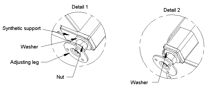
Kal-fire built-in fires are equipped with four level adjusting legs.
These have to be mounted before installing the appliance.
Please follow steps as well as drawings underneath for mounting the adjusting legs. 1. The threaded synthetic support has been factory-mounted.
2. The adjusting leg has to be screwed into the thread by means of
Make sure that there is always an air slot of at least 2 cm underneath
the appliance, so that convection and combustion air can flow freely. 9. Distances to combustible parts The drawing underneath shows an overview of minimum distances to be observed to the different external parts.
1. Between built-in wardrobes and surrounding, a minimum
comes into contact with the surrounding,
the intermediate room should be at least 1
combustible parts, such as furniture must be at least 80 cm.
4. If a radiation protection is mounted between the combustible
The heat-insulating materials that may be used, must meet certain
quality standards. We strongly recommend making sure that heat-
insulating materials resist height temperatures (at least 700° C), else a strong smell will be produced while heating. If possible, use ceramic fibre or rigid rock-wool panels with fibres
agglomerated with a binder. This will prevent that possible loose insulation parts will circulate in the convection system.
To be sure, use the Kal-fire ceramic insulating 2,5 cm thick, packed in
boxes of 732 cm x 62 cm. (Article code: ACCE SUPERWOO) 11. Insulations Mind! Insulation regulations differ from country to country. Always inform on nationally applicable standards and observe these. Points of special interest:
In all circumstances, make sure that convection air inlets at the
side and at the back in the lower part of the built-in fire are never obstructed.
Make sure that insulating materials are properly fixed, so that
The surrounding of the built-in fire can be constructed with various
materials. Do make sure that applied materials have the following
− Resistant against temperature of at least 700 °C
− Free from products that may evaporate and as such cause
− Retain their shape, also after being exposed to temperature
Points of special interest: The surrounding may not come in direct contact with the built-in fire,
but it must be self-supporting. Joints between built-in fire and
surrounding have to be sealed with heat-resistant glass fibre or ceramic sealing cord. In order to easily build a stable span above the door of the built-in fire, Kal-fire has a mantel iron for each type of built-in fire. This
mantel iron may never be fixed to the built-in fire, but to the side of the surrounding and to the ceiling or the wall by means of rods.
Pay attention to the fact that after insertion, it must still be possible
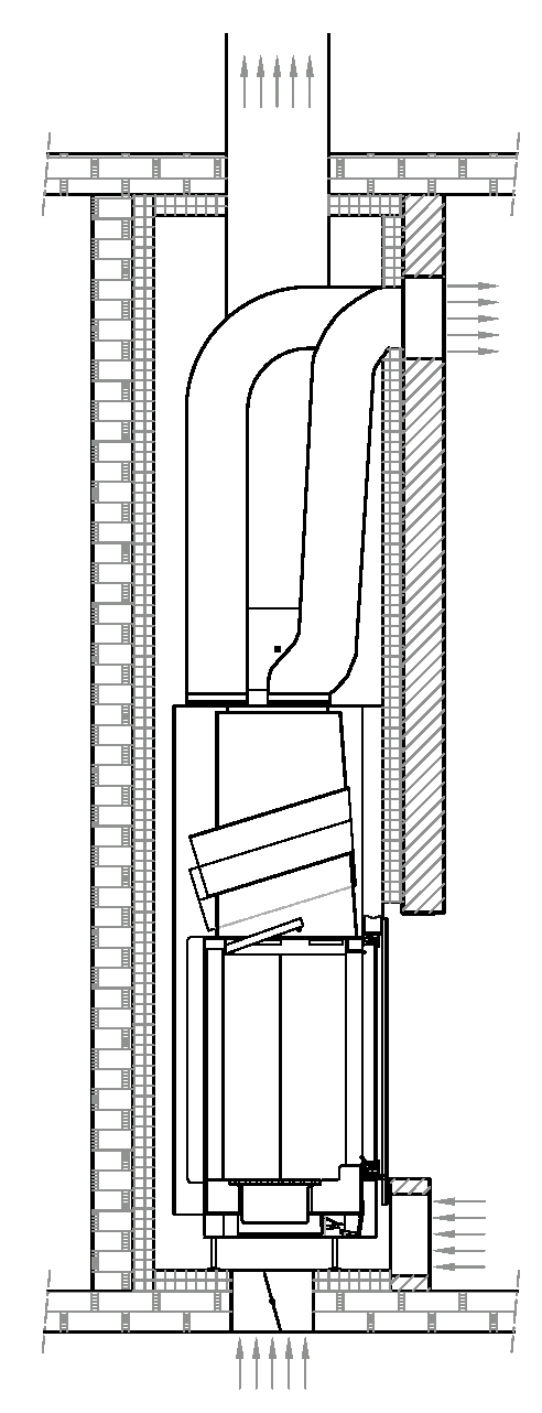
The drawing on the next page represents a crosscut of a possible
Make sure the surround is finished with materials that do not contain any synthetic parts. These may discolour under the influence of
Before fully completing the surrounding, make sure it is clean and
free of dust at the inside. We recommend vacuum cleaning the inside. Else, dust particles will be taken along in the airflow of the convection system, which may lead to nuisance.
Connection to Insulation for protecting the ceiling Insulation for protecting the Outlet for convection Aluminium hoses for outflowing convection air Exhaust Valv Mantel out of fire resistant material Insulation back wall Mantel iron may not be in contact with the appliance Inlet room air for convection flow Insulation Supply of fresh outside air
The appliances are equipped with a removable baffle plate. This baffle plate is situated above the hood, just underneath the heat
exchanger. This baffle plate sees to an optimal combustion by providing a higher
temperature in the combustion room. When the following events occur, it may be necessary to remove or to
reduce the size of the baffle plate. •
Smoke return when starting the appliance
Quick and extreme pollution of windowpane.
If it appears that the baffle plate must be adapted, proceed as follows.
Step 1
Remove the baffle plate and check if the problem is solved.
If removing the baffle plate does not resolve the problem, it is situated somewhere else. If the problem is resolved, proceed with the next step.
Step 2
Cut off a one centimetre wide strip from the front of the baffle plate. Mind! Do not cut off too much, the baffle plate always has to lie onto
the brace. Step 3 Check if the problem has been resolved. If not, proceed with the next step. Step4 If it is no longer possible to cut off anything at the front side because
otherwise the baffle plate will no longer fit onto the brace, cut off 1 cm at the side each time.
Make sure to always work in a symmetric way (cut off the same size at the left-side and the right-side).
Kal-fire B.V.
ARTICLE IN PRESS Urologic Oncology: Seminars and Original Investigations xx (2007) xxx–xxxSexual intimacy in heterosexual couples after prostate cancer treatment:What we know and what we still need to learnAndrea M. Beck, M.Sc.a,*, John W. Robinson, Ph.D.a,b, Linda E. Carlson, Ph.D.a,ba Department of Psychology, University of Calgary and Tom Baker Cancer Centre, Calgary, Alberta, C
BOLETIM INFORMATIVO DO GBM - ANO V - No. 18 Editorial O 20º Congresso Mundial de Dermatologia apresentou um número significativo de temas relacionados à oncologia cutânea. Foram oito simpósios e seis sessões interativas dedicados particularmente aos melanomas, cânceres cutâneos não melanomas e linfomas. As abordagens foram abrangentes e discorreram sobre epidemiologia, co
 Table of contents
  Congratulations on the purchase of your Kal-fire fireplace.
Read this manual carefully before installing and using the fireplace.
Always keep this manual close to your fireplace
Congratulations on the purchase of your Kal-fire fireplace.
Read this manual carefully before installing and using the fireplace.
Always keep this manual close to your fireplace  General building regulations of the country in question.
2. Verifications before installation •
Verify the delivered products on completeness and damage
immediately on receipt. Possible defects have to be notified
General building regulations of the country in question.
2. Verifications before installation •
Verify the delivered products on completeness and damage
immediately on receipt. Possible defects have to be notified 
 As manufacturer of built-in fires, we generally recommend that all
installations should dispose of sufficient a quantity of outside air. Else a trouble-free heating will not be possible.
If on the basis of calculations for combustion air, lower values are obtained, installation is done entirely at the risk of the installer.
Open fires may be installed or set up in above-mentioned rooms only if at least 360 m³ of combustion air per hour and per m² of fire box
opening can enter over an aeration duct, which can be closed by an
See list page 7 for correct diameter.
As manufacturer of built-in fires, we generally recommend that all
installations should dispose of sufficient a quantity of outside air. Else a trouble-free heating will not be possible.
If on the basis of calculations for combustion air, lower values are obtained, installation is done entirely at the risk of the installer.
Open fires may be installed or set up in above-mentioned rooms only if at least 360 m³ of combustion air per hour and per m² of fire box
opening can enter over an aeration duct, which can be closed by an
See list page 7 for correct diameter.  The Kal-fire built-is fire is provided with a convection system, which
heats up "cold" air from the room by means of a heat exchanger, and
leads "warm" air back into the room. When fitting the built-in fire, it is imperative to connect all warm air
connecting openings at the top of the built-in fire. For this purpose, use non-combustible aluminium flexible hoses. Make sure that each
hose has the same resistance (read: length, diameter, number of
bends), otherwise the convection flow will only occur partially or not at all. If separate connecting pieces are blocked or differ in resistance,
uniformity and temperature of the convection air is no longer
warranted by the manufacturer. For the convection system to work, it is imperative to provide grates at the bottom of the built-in fire. These must have the same flow as
the grates used for evacuating the warm air at the top. The system must be in balance. It is not necessary to connect the convection air
to the appliance at the bottom, the air, however, must be able to flow freely into the convection mantel.
Attention the in- and outlet openings for the convection air need to be in the same pressure zone. (room)
Use non-lockable grates. Mount these grates at least 30 cm from the
ceiling or the wall. No combustible parts may be situated within an area of 30 cm next to and 50 cm above the outlet grates. A built-in kit with all necessary parts for a correct installation is available at Kal-fire.
The Kal-fire built-is fire is provided with a convection system, which
heats up "cold" air from the room by means of a heat exchanger, and
leads "warm" air back into the room. When fitting the built-in fire, it is imperative to connect all warm air
connecting openings at the top of the built-in fire. For this purpose, use non-combustible aluminium flexible hoses. Make sure that each
hose has the same resistance (read: length, diameter, number of
bends), otherwise the convection flow will only occur partially or not at all. If separate connecting pieces are blocked or differ in resistance,
uniformity and temperature of the convection air is no longer
warranted by the manufacturer. For the convection system to work, it is imperative to provide grates at the bottom of the built-in fire. These must have the same flow as
the grates used for evacuating the warm air at the top. The system must be in balance. It is not necessary to connect the convection air
to the appliance at the bottom, the air, however, must be able to flow freely into the convection mantel.
Attention the in- and outlet openings for the convection air need to be in the same pressure zone. (room)
Use non-lockable grates. Mount these grates at least 30 cm from the
ceiling or the wall. No combustible parts may be situated within an area of 30 cm next to and 50 cm above the outlet grates. A built-in kit with all necessary parts for a correct installation is available at Kal-fire.
 Each built-in fire must be connected to its proper chimney. The
effective chimney height must at least be 4 meters, starting from the
point where the flue duct is mounted onto the built-in fire. The table underneath shows chimney diameter and firebox per model:
Kal-fire Heat
Each built-in fire must be connected to its proper chimney. The
effective chimney height must at least be 4 meters, starting from the
point where the flue duct is mounted onto the built-in fire. The table underneath shows chimney diameter and firebox per model:
Kal-fire Heat  Should you wish to deviate from the chimney diameters as mentioned in the table, you can use the formulae underneath to calculate a
possible reduced diameter. This reduction may have the following values at the most: •
Chimney diameters of 180 mm may be reduced by 30 mm.
Chimney diameters of 200 mm may be reduced by 20 mm.
Chimney diameters of 250 and 300 mm may be reduced by 50
Mind! This reduction must be applied immediately behind the exhaust valve and not further along the chimney. In case of doubt, always
use the connection diameter as indicated on the appliance.
Hsch = chimney height in meters, measured from the top of the
e = influence factor between 0.2 and 0.6 determined by the
0.2 in case of a perfect chimney, straight above the fire.
Absolutely avoid horizontal outlets, a possible displacement should be realised by movable elbows with a change of direction of 45° at the most.
Chimney insulation is highly recommendable, it reduces the risk of
condensation of the flue gases and promotes draught. Kal-fire recommends the use of the Kal-fire stainless steel insulated chimney
duct. We recommend not mounting larger chimney diameters than the
connection fitted on the built-in fire. Mounting larger chimney diameters may lead to the following problems:
− Too rash and uncontrolled a combustion.
Should you wish to deviate from the chimney diameters as mentioned in the table, you can use the formulae underneath to calculate a
possible reduced diameter. This reduction may have the following values at the most: •
Chimney diameters of 180 mm may be reduced by 30 mm.
Chimney diameters of 200 mm may be reduced by 20 mm.
Chimney diameters of 250 and 300 mm may be reduced by 50
Mind! This reduction must be applied immediately behind the exhaust valve and not further along the chimney. In case of doubt, always
use the connection diameter as indicated on the appliance.
Hsch = chimney height in meters, measured from the top of the
e = influence factor between 0.2 and 0.6 determined by the
0.2 in case of a perfect chimney, straight above the fire.
Absolutely avoid horizontal outlets, a possible displacement should be realised by movable elbows with a change of direction of 45° at the most.
Chimney insulation is highly recommendable, it reduces the risk of
condensation of the flue gases and promotes draught. Kal-fire recommends the use of the Kal-fire stainless steel insulated chimney
duct. We recommend not mounting larger chimney diameters than the
connection fitted on the built-in fire. Mounting larger chimney diameters may lead to the following problems:
− Too rash and uncontrolled a combustion.
 In case the chimney features an extremely high draught, a draught
controller should be installed since the delivered chimney valve may be insufficient. A chimney with too strong a draught may lead to a
quick and uncontrolled combustion, a restless fire and a quickly polluted windowpane. If contrary to the above-mentioned instructions, other chimney
diameters are applied, this will be done at the sole risk of the installer. Moreover, this may lead to problems such as: smoke
return to the room when the door is opened, difficult lighting of the appliance, etc
7. Exhaust valve Each appliance is delivered with a exhaust valve, which has to be
mounted onto the built-in fire. The control knob is connected to the exhaust valve by means of a rod and is mounted into the surrounds. Check whether the instruction onto the knob corresponds with reality.
Make sure the customer is acquainted with the correct use of the exhaust valve, see user's manual for this purpose.
In case the chimney features an extremely high draught, a draught
controller should be installed since the delivered chimney valve may be insufficient. A chimney with too strong a draught may lead to a
quick and uncontrolled combustion, a restless fire and a quickly polluted windowpane. If contrary to the above-mentioned instructions, other chimney
diameters are applied, this will be done at the sole risk of the installer. Moreover, this may lead to problems such as: smoke
return to the room when the door is opened, difficult lighting of the appliance, etc
7. Exhaust valve Each appliance is delivered with a exhaust valve, which has to be
mounted onto the built-in fire. The control knob is connected to the exhaust valve by means of a rod and is mounted into the surrounds. Check whether the instruction onto the knob corresponds with reality.
Make sure the customer is acquainted with the correct use of the exhaust valve, see user's manual for this purpose.


 Kal-fire built-in fires are equipped with four level adjusting legs.
These have to be mounted before installing the appliance.
Please follow steps as well as drawings underneath for mounting the adjusting legs. 1. The threaded synthetic support has been factory-mounted.
2. The adjusting leg has to be screwed into the thread by means of
Make sure that there is always an air slot of at least 2 cm underneath
the appliance, so that convection and combustion air can flow freely. 9. Distances to combustible parts The drawing underneath shows an overview of minimum distances to be observed to the different external parts.
1. Between built-in wardrobes and surrounding, a minimum
comes into contact with the surrounding,
the intermediate room should be at least 1
combustible parts, such as furniture must be at least 80 cm.
4. If a radiation protection is mounted between the combustible
Kal-fire built-in fires are equipped with four level adjusting legs.
These have to be mounted before installing the appliance.
Please follow steps as well as drawings underneath for mounting the adjusting legs. 1. The threaded synthetic support has been factory-mounted.
2. The adjusting leg has to be screwed into the thread by means of
Make sure that there is always an air slot of at least 2 cm underneath
the appliance, so that convection and combustion air can flow freely. 9. Distances to combustible parts The drawing underneath shows an overview of minimum distances to be observed to the different external parts.
1. Between built-in wardrobes and surrounding, a minimum
comes into contact with the surrounding,
the intermediate room should be at least 1
combustible parts, such as furniture must be at least 80 cm.
4. If a radiation protection is mounted between the combustible
 The heat-insulating materials that may be used, must meet certain
quality standards. We strongly recommend making sure that heat-
insulating materials resist height temperatures (at least 700° C), else a strong smell will be produced while heating. If possible, use ceramic fibre or rigid rock-wool panels with fibres
agglomerated with a binder. This will prevent that possible loose insulation parts will circulate in the convection system.
To be sure, use the Kal-fire ceramic insulating 2,5 cm thick, packed in
boxes of 732 cm x 62 cm. (Article code: ACCE SUPERWOO) 11. Insulations Mind! Insulation regulations differ from country to country. Always inform on nationally applicable standards and observe these. Points of special interest:
In all circumstances, make sure that convection air inlets at the
side and at the back in the lower part of the built-in fire are never obstructed.
Make sure that insulating materials are properly fixed, so that
The heat-insulating materials that may be used, must meet certain
quality standards. We strongly recommend making sure that heat-
insulating materials resist height temperatures (at least 700° C), else a strong smell will be produced while heating. If possible, use ceramic fibre or rigid rock-wool panels with fibres
agglomerated with a binder. This will prevent that possible loose insulation parts will circulate in the convection system.
To be sure, use the Kal-fire ceramic insulating 2,5 cm thick, packed in
boxes of 732 cm x 62 cm. (Article code: ACCE SUPERWOO) 11. Insulations Mind! Insulation regulations differ from country to country. Always inform on nationally applicable standards and observe these. Points of special interest:
In all circumstances, make sure that convection air inlets at the
side and at the back in the lower part of the built-in fire are never obstructed.
Make sure that insulating materials are properly fixed, so that
 The surrounding of the built-in fire can be constructed with various
materials. Do make sure that applied materials have the following
− Resistant against temperature of at least 700 °C
− Free from products that may evaporate and as such cause
− Retain their shape, also after being exposed to temperature
The surrounding of the built-in fire can be constructed with various
materials. Do make sure that applied materials have the following
− Resistant against temperature of at least 700 °C
− Free from products that may evaporate and as such cause
− Retain their shape, also after being exposed to temperature

 Connection to
  The appliances are equipped with a removable baffle plate. This baffle plate is situated above the hood, just underneath the heat
exchanger. This baffle plate sees to an optimal combustion by providing a higher
temperature in the combustion room. When the following events occur, it may be necessary to remove or to
reduce the size of the baffle plate. •
Smoke return when starting the appliance
Quick and extreme pollution of windowpane.
If it appears that the baffle plate must be adapted, proceed as follows.
The appliances are equipped with a removable baffle plate. This baffle plate is situated above the hood, just underneath the heat
exchanger. This baffle plate sees to an optimal combustion by providing a higher
temperature in the combustion room. When the following events occur, it may be necessary to remove or to
reduce the size of the baffle plate. •
Smoke return when starting the appliance
Quick and extreme pollution of windowpane.
If it appears that the baffle plate must be adapted, proceed as follows.
 Kal-fire B.V.